Differential Amplifier | Common-mode Rejection Ratio | Common and Differential-mode Signals
Differential Amplifier
A differential amplifier is a circuit that can accept two input signals and amplify the difference between these two input signals. Differential amplifier (DA) is key to the operation of OP-Amp, we shall discuss this in detail.
 |
| Block Diagram of Differential Amplifier |
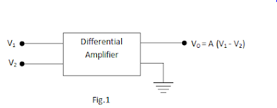
The block diagram of a differential amplifier is shown in above fig. There are two input voltages v1 and v2. This amplifier amplifies the difference between the two input voltages. Therefore, the output voltage is Vo = A(v1-v2) where A is the voltage gain of the amplifier.
Basic Circuit of Differential Amplifier
The basics circuit of a differential amplifier is shown below in Fig. It consists of two transistors Q1 and Q2 that have identical characteristics. They share a common positive supply VCC, common emitter resistor RC and common negative supply VEE.
 |
| Symbol of Differential Amplifier |
The differential amplifier (DA) is a two input terminal device using at least two transistors and there are two output terminals marked ( Vout 1) and ( Vout 2). In Differential Amplifier, transistor T1 and T2 are matched so that their characteristics are the same. Both the collector resistors RC1 and RC2 are also equal. The equality of the matched circuit components makes the DA circuit arrangement completely symmetrical. The signal is applied either to one input of DA and the other input is grounded, it is called single-ended input arrangement or the signals are applied to both inputs of DA, it is called double-ended input arrangement. Similarly, the output of DA can be taken from either one of the output terminals and ground (single-ended output arrangement) or two output terminals (double-ended output arrangement). Generally, the differential amplifier (DA) is operated for single-ended output.
Operation of Differential Amplifier
The operation of differential amplifier can be easily understood by giving one input (say at 1 as shown in the below figure) and which produces output at both the output terminals.
 |
| Operation of Differential Amplifier |
If the input signal (1) is supplied to the base of transistor Q1, then a high voltage drop appears across the resistor connected to the transistor Q1 collector terminal which will get less positive. If no input signal (1) is supplied to the base of transistor Q1, then a low voltage drop appears across the resistor connected to the transistor Q1 collector terminal which will get more positive. Thus, we can say that the inverting output appearing across collector terminal of transistor Q1 is based on the input signal 1 supplied at the base terminal of Q1.
If Q1 is turned ON by applying the positive value of 1, then the current passing through emitter resistance increases as the emitter current & collector current are almost equal. Thus, if the voltage drop across emitter resistance increases, then the emitter of both the transistors goes in a positive direction. If the transistor Q2 emitter is positive, then the base of Q2 will be negative and in this condition, current conduction is less.
Thus, there will be less voltage drop across resistor connected at the collector terminal of transistor Q2. Hence, for the given positive input signal collector of Q2 will go in a positive direction. Thus, we can say that the non-inverting output appearing across collector terminal of transistor Q2 is based on the input signal applied at the base of Q1.
The amplification can be driven differentially by taking output between the collector terminals of transistors Q1 and Q2. From the above circuit diagram, assuming all the characteristics of transistors Q1 & Q2 are identical and if base voltages Vb1 is equal to Vb2 (base voltage of transistor Q1 is equal to base voltage of transistor Q2), then emitter currents of both transistors will be equal (Iem1=Iem2). Thus, total emitter current will be equal to the sum of emitter currents of Q1 (em1) and Q2 (em2).
Common-mode and Differential-mode Signals
(i) Common-mode signals
When the input signals to a DA are in phase and exactly equal in amplitude, they are called common-mode signals. The common-mode signals are rejected By the differential amplifier. It is because a differential amplifier amplifies the difference between the two signals between (v1-v2) and for common-mode signals, this differences zero. Note that for common mode operations, v1 = v2.
(ii) Differential-mode signals
When the input signals to a DA are 180ᵒ out of phase and exactly equal in amplitude, They are called differential-mode signals. The differential-mode signals are amplified by the differential amplifier. It is because the difference in the signals is twice the value of each signal. For differential-mode signals v1 = -v2.
Voltage Gains of Differential Amplifier
The voltage gain of a Differential Amplifier operating in
differential mode is called differential mode voltage gain and is denoted
by ADM. The voltage gain of Differential Amplifier in
common-mode is called common-mode voltage gain it is denoted by ACM.
Common-mode Rejection Ratio (CMRR)
CMRR = ADM/ACM
Very often, the CMRR is expressed in decibels (dB). The decibel measure for CMRR is given by;
CMRRdB = `20\log_{10}(A_{DM}/A_{CM})`
CMRRdB = `20 \log_{10}`(CMRR)
Applications of Differential Amplifier
There are numerous application of differential amplifier in practical circuits, signal amplification, controlling of motors & servo motors, input stage emitter coupled logic, switch, and so on are common applications of the differential amplifier circuit.

