4-to-1 Multiplexer and Demultiplexer
Multiplexer
A multiplexer is a circuit with many inputs but only one output. Multiplex means many into one. Multiplexer is also called as Mux. By applying control signals, we can steer any input to the output. Thus it is also called a data selector and control inputs are termed select inputs.
The circuit has n input signals, m control signals and 1 output signal. Note that, m control signals can select at the most 2m input signals thus n < 2m.
 |
| Block diagram of n-to-1 multiplexer |
4-to-1 Multiplexer
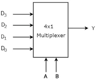
The 4-to-1 multiplexer comprises 4-input bits, 1- output bit, and 2- control bits. The four input bits are namely D0, D1, D2 and D3, respectively; only one of the input bit is transmitted to the output. The output ‘Y’ depends on the value of control input AB. The control bit AB decides which of the input data bit should transmit the output. The following figure shows the 4-to-1 multiplexer circuit diagram using AND gates. For example, when the control bits AB =00, then the higher AND gate are allowed while remaining AND gates are restricted. Thus, data input D0 is transmitted to the output ‘Y’.
 |
| 4-to-1 Multiplexer |
If the control input is changed to 11, then all gates are restricted except the bottom AND gate. In this case, D3 is transmitted to the output and Y=D0. If the control input is changed to AB =11, all gates are disabled except the bottom AND gate. In this case, D3 is transmitted to the output and Y = D3.The best example of 4-to-1 multiplexer is IC 74153. In this IC, the output is same as the input. Another example of 4-to-1 multiplexer is IC 45352. In this IC, the output is the compliment of the input. The circuit diagram of a 4-to-1 multiplexer is shown in Fig.
 |
| 4-to-1 Multiplexer |
 |
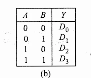
| Truth Table |
The logic equation of this circuit is given as follow :
Y=A'B'D0+A'BD1+AB'D2+ABD3
Clearly, it will give a SOP representation, each AND gate generating a product term, which finally are sumed by OR gate.
Demultiplexer
A demultiplexer is a device, that has one input and multiple output lines which is used to send a signal to one of the various devices. Demultiplex means one into many. By applying control signals, we can steer the input signal to one of the output lines. The most prominent distinction between a multiplexer and demultiplexer is that a multiplexer takes two or a lot of signals and encodes them on a wire, whereas a demultiplexer reverses what the multiplexer does.
 |
| Block Diagram of 1-to-n Demultiplexer |
1-to-4 Demultiplexer
The 1-to-4 demultiplexer comprises 1-input bit, 4-output bits and 2–control bits. The 1-to-4 demultiplexer circuit diagram is shown below.
 |
| 1-to-4 Demultiplexer |
The input bit is considered as Data D. This data bit is transmitted to the data bit of the output lines, which depends on the AB value and the control input. When the control input AB = 01, the upper second AND gate is permitted while the remaining AND gates are restricted. Thus, only data bit D is transmitted to the output and Y1 = Data.
If the data bit D is low, the output Y1 is low. If data bit D is high, the output Y1 is high. The value of the output Y1 depends upon the value of data bit D, the remaining outputs are in a low state. If the control input changes to AB = 10, then all the gates are restricted except the third AND gate from the top. Then, data bit D is transmitted only to the output Y2; and, Y2 = Data. The best example of 1-to-4 demultiplexer is IC 74155.


