Digital Counter | Synchronous and Asynchronous
Counter
A register that goes through a predetermined sequence of states upon the application of input pulses is called a counter. The input pulses may be clock pulses or may originate from an external source. They may occur at uniform internals of time or at random. They are used for counting the number of occurrence of an event and are useful for generating timing signals to control the sequence of operations and digital computers.
A counter that follows the battery number sequence is called a binary counter. An n-bit binary counter is a resistor of n flip-flops and associated Gates that follows the sequence of states according to the binary count of n-bits, from 0 to 2n . A simpler alternative design procedures may be carried out from a direct inspection of the sequence of states that the resister must undergo to achieve statewide count.
A counter as the name implies, counts the sequence of numbers depending on the number of clock pulses received counters can be realized using flip-flops.
Types of Counter
Counters are of two types depending on to which flip-flop in the counter circuit the clock is applied. They are
- Asynchronous counter (also called ripple counter)
- Synchronous counter.
(i) Asynchronous Counter
When the output of a flip-flop is used as the clock input for the next flip-flop, we call the counter a ripple counter or asynchronous counter. A binary ripple counter can be constructed using clocked JK flip-flops.
 |
| Circuit diagram and Waveform of Asynchronous counter |
Asynchronous counters are called ripple counters possibly because the clock pulse appear to be rippling their way through the flip-flops. A 3-bit ripple counter counts clock pulses and produces the output from 0 to 7. Observe that the clock is applied only to the first flip-flop. The J and K inputs are both held at a high level, so that the flip-flops have complementary capabilities. Observe that the first flip-flip's output (Qo) changes at the rising age of the clock. The second flip-flop's output changes as the following age of (Qo) and so on.
(ii) Synchronous Counter
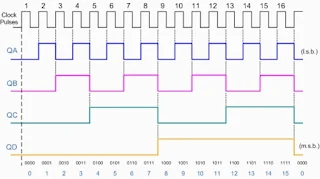
Synchronous binary counter have a regular patterns, as can be seen from the 4-bit binary counter. The CLK inputs of all flip-flops received the common clock. If the count enable is 0, all J and K inputs are maintained at 0 and the output of the counter does not change. The first stage Ao is complemented when the country is enabled and the clock goes through a positive transition. Each of the other three flip-flops are complemented when all previous least significant flip-flops are equal to 1 and the count is enabled. The chain of AND Gate generate the required logic for the J and K inputs. The output carry can be used to extend the counter to more stage, with each stage having an additional flip-flop and an AND Gate.
 |
| Circuit diagram of synchronous counter |
 |
| Wave form of Synchronous Counter |

