Combinational Circuits | Half Adder, Full Adder, Circuit Diagram
Combinational Circuits
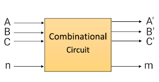
A combinational circuit is a connected arrangement of logic gates with a set of inputs and outputs. At any given time, the binary values of the outputs are a function of the binary combination of the input. The n binary input variables come from an external source, the m binary output variables go to an external destination and there is an interconnection of logic gates in between.
A combinational circuit transfer binary information from the given input data. A combinational circuit that performs the arithmetic addition of two bits is called a half-adder. One that performs the addition of three bits is called a full-adder. The name of the former stems from the fact that two half adder are needed to implement a full-adder. A block diagram of combinational circuit is shown in Fig.
 | |
|
A combinational circuit can be described by a truth table showing the binary relationship between the n input variables and m output variable. The truth table list the corresponding output binary values for each of the 2n input combinations.
Half-Adder
The most basic digital arithmetic circuit is the addition of two binary digits. A combinational circuit that performs the arithmetic addition of two bits is called a half-adder. The output of the exclusive-OR gate is called the SUM, while the output of the AND gate is the carry. The AND gate produces a high output only when both inputs are high. The exclusive-OR gate produces a high output if either input, but not both, is high.
The input variables of a half-adder are called the augend and addend bits. The output variables the sum and carry. When we add 1 and 1, we get sum=0 and carry=1. The logic diagram is shown in Fig. It consists of an exclusive-OR gate and an AND gate.
 |
| Logic circuit of half-adder |
 |
| Truth table of Half-Adder |
Full-Adder
A full-Adder is a combinational circuit that forms the arithmetic sum of three input bits. One that performs the addition of three bits is called a full-adder. It consists of three input and two outputs. Two outputs are necessary because the arithmetic sum of three binary digits ranges in value from 0 to 3, and binary 2 or 3 require two digits. When all inputs bits are 0, the output is 0. The S output is equal to 1 when only 1 input is equal to one or when all three inputs are equal to 1. The C output has a carry of 1 if two or three inputs are equal to 1. The logic diagram of Full-Adder is shown in Fig.
 |
| Logic circuit of full-adder |
 |
| Truth Table of Full Adder |
Multiplexers
Multiplexer is a special type of combinational circuit. There are n-data inputs, one output and m select inputs with 2m = n. It is a digital circuit which selects one of the n data inputs and routes it to the output. The selection of one of the n inputs is done by the selected inputs. Depending on the digital code applied at the selected inputs, one out of n data sources is selected and transmitted to the single output Y. E is called the strobe or enable input which is useful for the cascading. It is generally an active low terminal that means it will perform the required operation when it is low.
Demultiplexers
A demultiplexer performs the reverse operation of a multiplexer i.e. it receives one input and distributes it over several outputs. It has only one input, n outputs, m select input. At a time only one output line is selected by the select lines and the input is transmitted to the selected output line. A demultiplexer is equivalent to a single pole multiple way switch.

