Half wave and Full wave Rectifier | Principle, Working, Limitations
What is a Rectifier?
A rectifier is a device which converts an alternating (AC) input voltage into a direct (DC) output voltage. Any electrical device which has a high resistance to current in one direction and low resistance to current in opposite direction possesses the ability to convert AC current into DC current.
Principle
A p-n junction diode offers very low resistance in forward bias and extremely high resistance in Reverse bias. Due to this property, a p-n junction diode primarily allows the flow of current only in one direction. So, if an alternating voltage is applied across a diode, the current flows only in that part of the cycles when the diode is forward biased. This property of p-n junction diode is used to rectify alternating voltages and the circuit used to this purpose is called a rectifier. p-n junction diode can be used either as (a) half wave rectifier or (b) full wave rectifier.
(a) Half-wave Rectifier
Construction
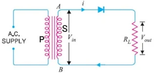
The arrangement for a half-wave rectifier is shown in Fig. The AC input voltage is fed across the primary coil P of a suitable step-down transformer. The secondary coil S of the transformer is connected to the semiconductor p-n junction diode D and a load resistance RL.
 |
| Half-wave rectifier |
Working Method
Let during the first half of AC input cycle, the end A of secondary S of transformer be at positive potential and end B at the negative potential. In this situation, the diode is forward biased and a current flows in the circuit. Consequently, an output voltage across load RL is obtained.
During the second half of AC input, the end A of secondary S of transformer is at negative potential and diode D is in reverse bias. So, no current flows through load RL and there is no output voltage across RL.
 |
In the next positive half-cycle of AC input, we again get the output and so on. Thus, we get output voltage as shown in Fig. Here, the output voltage, though still varying in magnitude, is restricted to only one direction and is said to be rectified. Since, the rectified output of the circuit is obtained only for half of the input AC wave, the device is called half-wave rectifier.
(b) Full-wave rectifier
A full-wave rectifier is the rectifier which rectifies both halves of each AC input cycle and gives a unidirectional output voltage continuously.
Construction
In a full-wave rectifier, we use two semiconductor diode which operate in a complimentary mode. The AC input supply is fed across the primary coil P of a centre tap transformer. The two ends A and B of the second S of the transformer are connected to the p-ends of the Diodes D1 and D2 respectively. A load resistance RL is connected between the n-terminal of both the Diodes and the center tapping O of the second of transformer. The DC output is obtained across load residence RL.
 |
| Full-wave rectifier |
Working Method
During the first half cycle of the input voltage, the terminal A is positive with respect to O while B is negative with respect to O. Diode first is forward bias and conducts while diode second is reverse bias and does not conduct, the current flow through RL from D To O. During the second half cycle, A is negative and B is positive with respect to O, thus diode first is reverse bias and diode second is forward biased. The current through RL is in the same direction as during the first half cycle. The resulting output current is a continuous series.
As we are getting output in positive half as well as negative half of AC input cycle, the rectifier is called a full wave rectifier. Obviously, this is a more efficient circuit for getting rectified voltage or current than a half wave rectifier.
Limitation of rectifier
Although full wave rectifier gives continuous output voltage/current in One direction, the rectified voltage is in the form of pulses of the shape of Half sinusoids. So, the output voltage is unidirectional but it does not have steady value. In fact, such a pulsating output has some AC ripple mixed with a pure DC voltage and to get pure DC voltage output, we must filter out the AC ripple by using some additional filter arrangement.


